Viking Johnson design and manufacture of couplings flange adaptors pipe connections repair and flow control products and shouldered and expansion joints for international water and gas markets. Vaibhav Patel-September 25 2014.

Solidworks Flange Coupling Cad Tutorials Part Design Assembly Drafting Of All Parts Youtube
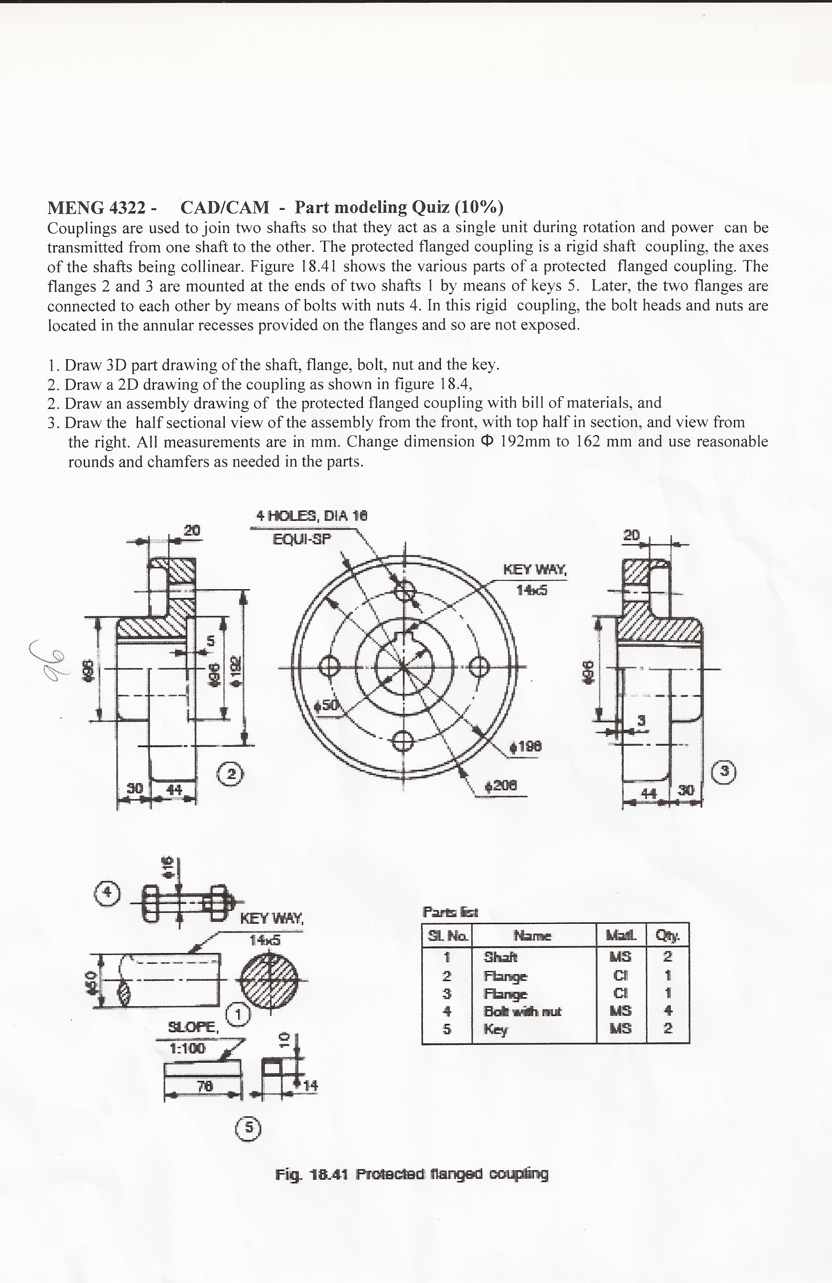
Following drawing shows the Protected type flanged coupling with proportions expressed in terms of.
. To draw various parts of Unprotected Flange Coupling and assemble the parts by 2D draw tool commands in AutoCAD 2010. Flange coupling 2d drawing. Here is the simple and easiest method for drawing FLANGE COUPLING ASSEMBLY in AutoCAD software.
Protected type flanged coupling. The two flanges are coupled together by means of bolts and nuts. Power is transmitted from driving shaft to flange on driving shaft through key from flange on driving shaft to the flange on driven shaft through bolts and then to the driven shaft through key again.
This video helps you to draw the assembled front and side view of flange coupling manuallyNow you can get ALL my drawings in PDFwith answer key on paymen. Home Tags Flange coupling adapter cad drawing. We are proud to inform that we had done some valuable programme on several colleges for past 10 years both in Anna University and Pondicherry University.
So it is very easy to calculate all the dimensions in. The flange couplings are of the following three types. Wednesday 30 Mar 2022 1718 PM GMT.
We are making a 3d design of flange coupling using CatiaV5 and analysing with Ansys18. Monday 28 Mar 2022 1909 PM GMT. We have a 2d designed drawing with required dimensions and components for assembly.
R AP MECH 90 ASSEMBLY DRAWING OF UNPROTECTED FLANGE COUPLING IN 2D EXPT NO. Flange Coupling Unprotected Creo part Design And Assembly. For Part C 3D environment should be used for parts and assembly and extract 2D views of assembly.
1 flange coupling Fig. For Part A and Part B 2D drafting environment should be used. What is flange coupling.
Training Video For professional Designer. Flange coupling - EG using AutoCAD Flange coupling assembly drawing step by step processTrailer. Engineering a driving coupling between rotating shafts that consists of flanges or half couplings one of which is fixed at the end of each shaft the two flanges being bolted together with a ring of bolts to complete the drive.
Httpsyoutubepmv5szpPks4For Design Related doubts mai. Coupling is a mechanical device used to couple the shaft for transmission of power from driving shaft to another driving shaft. The major goal of this paper is to secure the design of flange coupling to transmit strength evaluating theoretical and analytical end result both.
Flange coupling adapter cad drawing. DEPARTMENT OF MECHANICAL ENGINEERING Computer Aided Machine Drawing Lab Manual By Ashok Kumar. The design o f pr otected type rigid flange coupling is as pe r standard design procedure which mainly co nsists of empirical relations.
Flange coupling consists of two flanges keyed to the shafts. In this types of shaft coupling the flange and hub are separately assembled together instead of a single part as flange coupling. Creo Part Design Assembly Learn In easy Way.
Viking Johnson design and manufacture of couplings flange adaptors pipe connections repair and flow control products and shouldered and expansion joints for international water and gas markets. Design of Flange Coupling. Gear couplings can transmit high torque because of the large size of the teeth.
Types of Flange Coupling. Design specification of coupling. The flange coupling is adopted to heavy loads and hence it is used on large shafting.
Design of Flange Coupling. How do you draw a. CATIA V5R21 software program is used to create the.
It is a member of 78xx series of fixed linear voltage. A beam coupling also known as helical coupling is a flexible coupling for transmitting torque between two shafts while allowing for angular misalignment parallel offset and even axial motion of one shaft relative to the other. This design utilizes a single piece of material and becomes flexible by removal of material along a spiral path resulting in a curved flexible beam of helical.
2D 3D models are now available. Using CAD Firstly we create constrained sketch with dimensions. The gear coupling is a modified version of the flange coupling.
The flanges are connected together by means of bolts arranged on a circle concentric to shaft. 2 flange coupling Fig. Flange coupling the use of ANSYS workbench 160.
This helps to bring the shafts into line and to maintain alignment. Reference to drawing we create individual components namely flangeboltnut and shaft. See All Design To Learn to Design and assemble The Parts in Diff Ways And Methods.
7806 is a voltage regulator integrated circuit. Unprotected type In this type of coupling each shaft is keyed to the boss of a flange with counter sunk key and both flanges are coupled together with rings of bolts. Grey cast Iron and Structural metal is used as flange coupling material.
By swivelling the compound rest belt transect advantages and disadvantages manufacturing processes knuckle joint 2d drawing with dimensions cim by jayakumar pdf. Flange coupling is a type of shaft coupling having two separate flanges which are mounted on the shaft end and both flanges are bolted together by means of nuts and bolts. Flange coupling is a type of Coupling used between rotating shafts that consists of flanges one of which is fixed at the end of each shaft the two flanges being bolted together with bolts fitted circumferentialy to.
Taking into consideration the service factor of 15 the design torque is given by Td 60 106 kW 2πn 15 60 106 375 15 2π 180 298415518 N mm 16Td πd 3 or 76 16 298415518 πd 3 Diameter of shaft d 5848 or 60 mm.

Flange Coupling Eg Using Autocad Flange Coupling Assembly Drawing Step By Step Process Youtube
Solved Couplings Are Used To Join Two Shafts So That They Chegg Com

2 D Flange Coupling Model Download Scientific Diagram

Detail Drawing Of Coupling Download Scientific Diagram

Flange Coupling From My York High School Mechanical Drawin Flickr

Machine Drawing Flange Coupling
Flange Coupling Transmission In Autocad Cad 44 58 Kb Bibliocad

Fcl 450 Flexible Flanged Shaft Coupling Nbk The Motion Control Components
0 komentar
Posting Komentar